Micro8088 build log
Overview
This is a build log of an IBM XT-compatible system called “Micro 8088”, designed by Sergey Kiselev.

micro8088 CPU card specifications:
- NEC V20 CPU (4.77 MHz, 7.16 MHz and 9.54 MHz CPU frequencies)
- Faraday FE2010A chipset
- 640 KiB RAM (+ XMS)
- PS/2 keyboard interface
- 8bit ISA interface
Other ISA cards in the system:
- Trident TVGA9000 VGA card
- XT-CF-Lite V4 card (XT-IDE ROM)
- Game Blaster (clone) sound card
- Aztech AZT2320 sound card
- ISA8019 network card
In operation
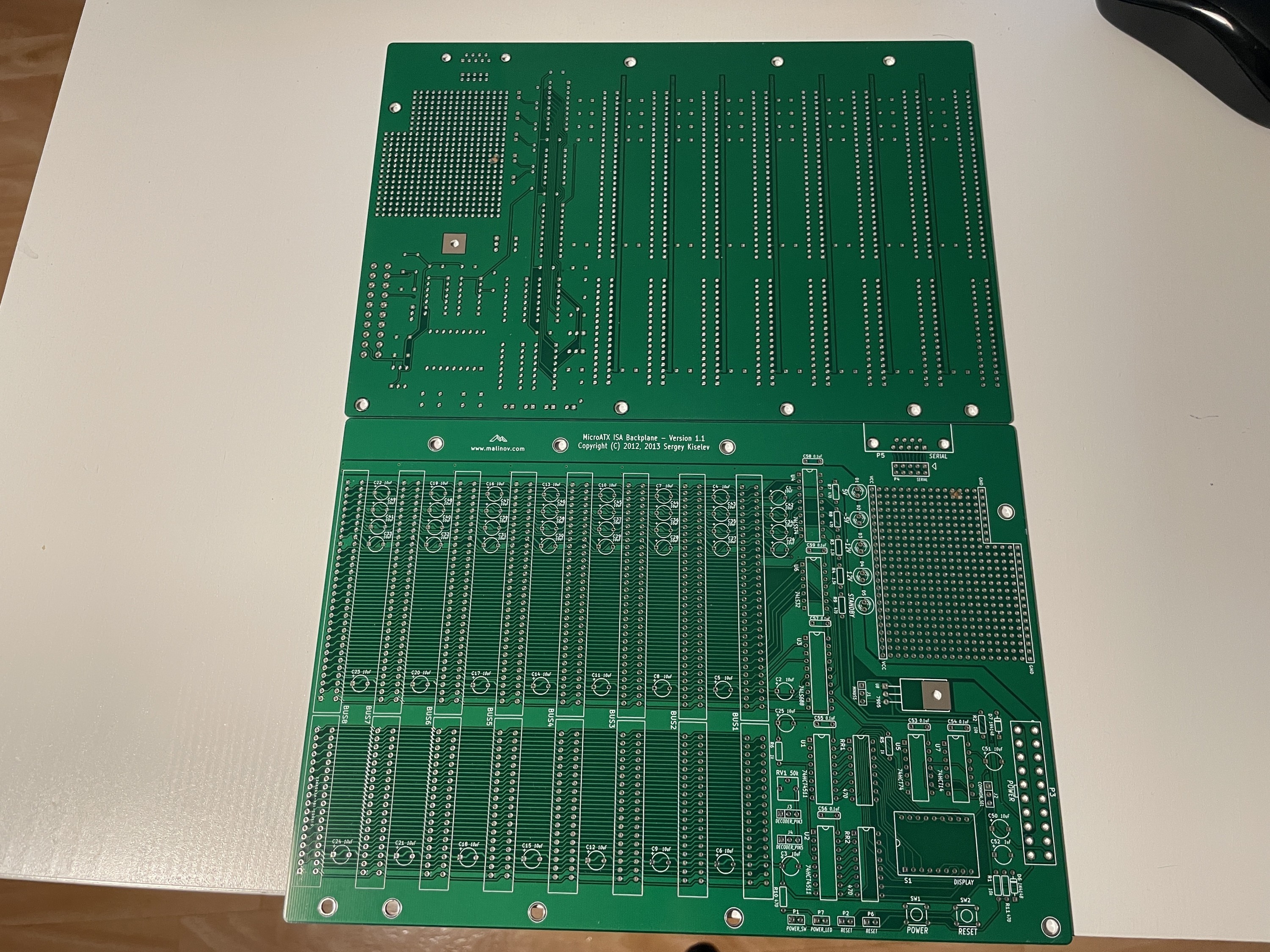
Backplane
The ISA backplane was also designed by Sergey Kiselev. It connects eight 16bit ISA slots in parallel.
The backplane is microATX form factor-compatible, includes a POST-code display and a -5V voltage regulator.

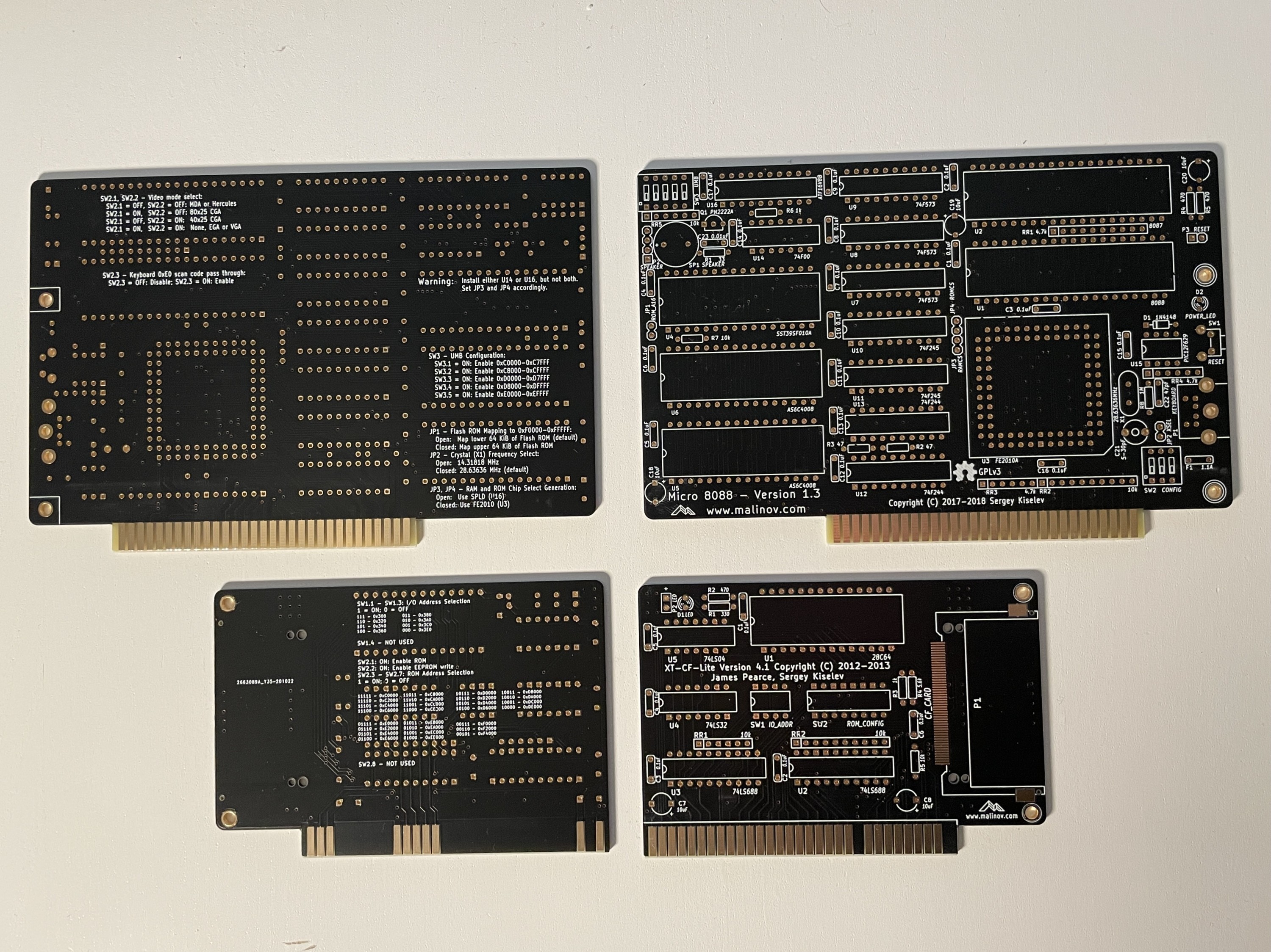
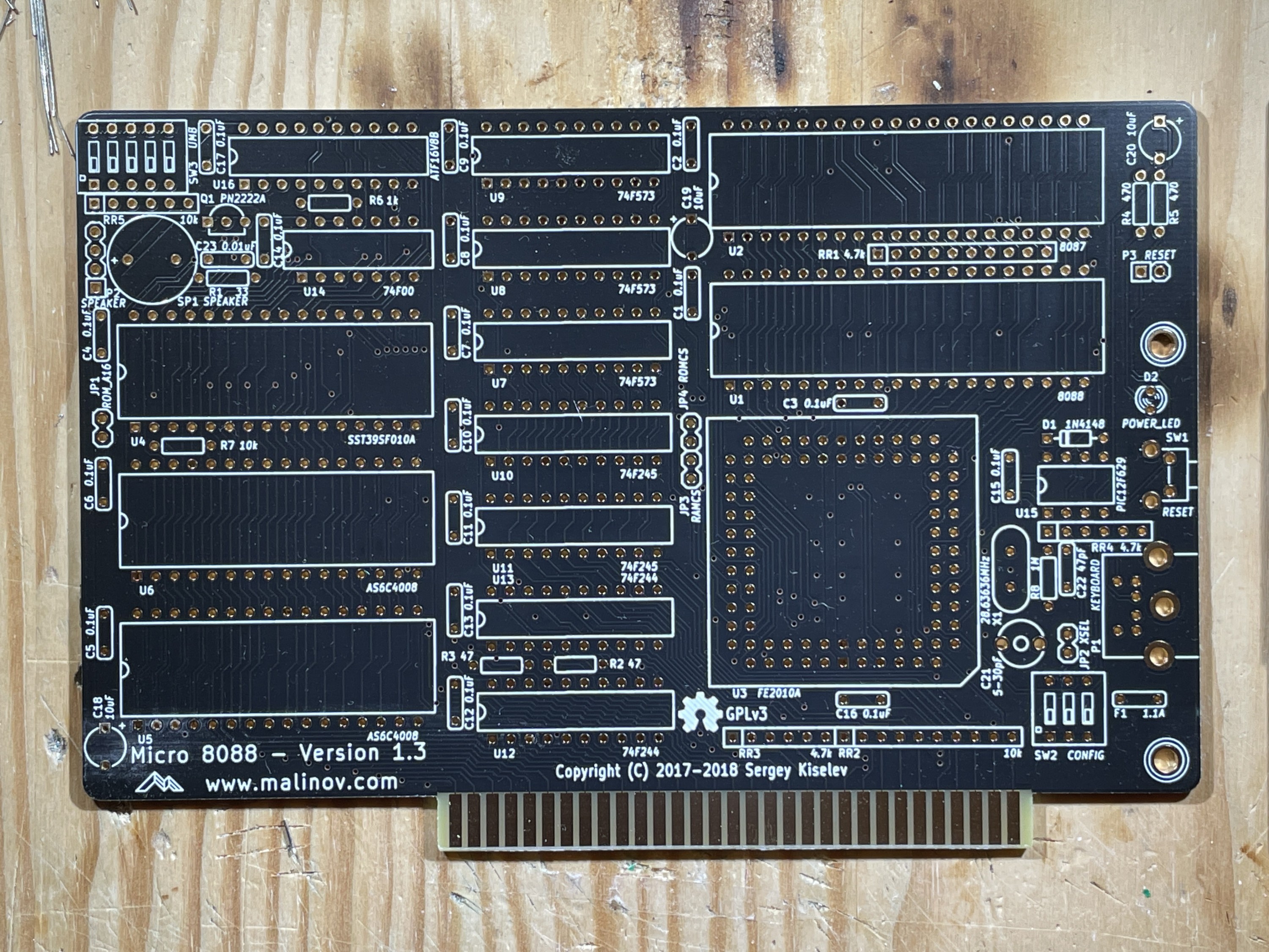
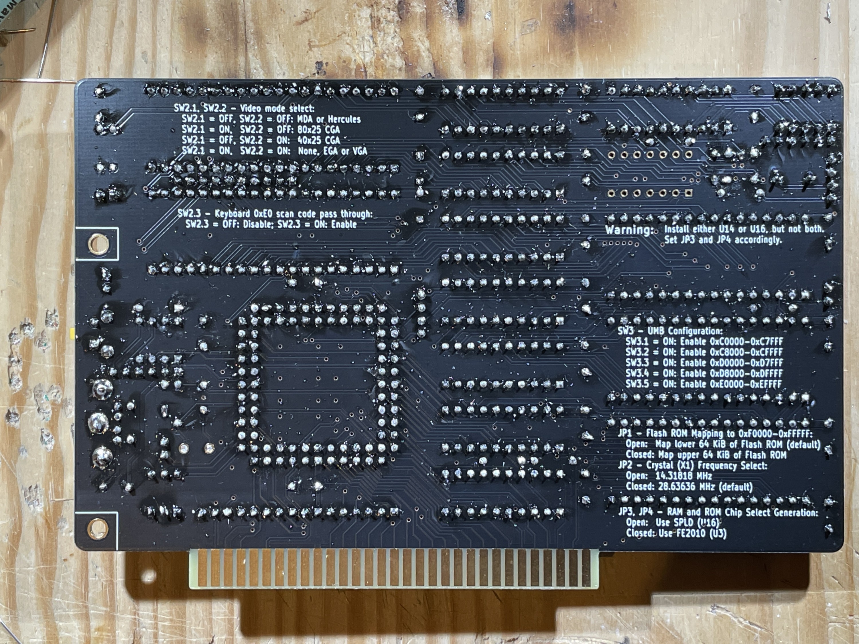
micro8088 CPU card
PCBs were ordered from JLCPCB, using ENIG (gold plating) and 45° chamfering (to enable insertion into the ISA slots).
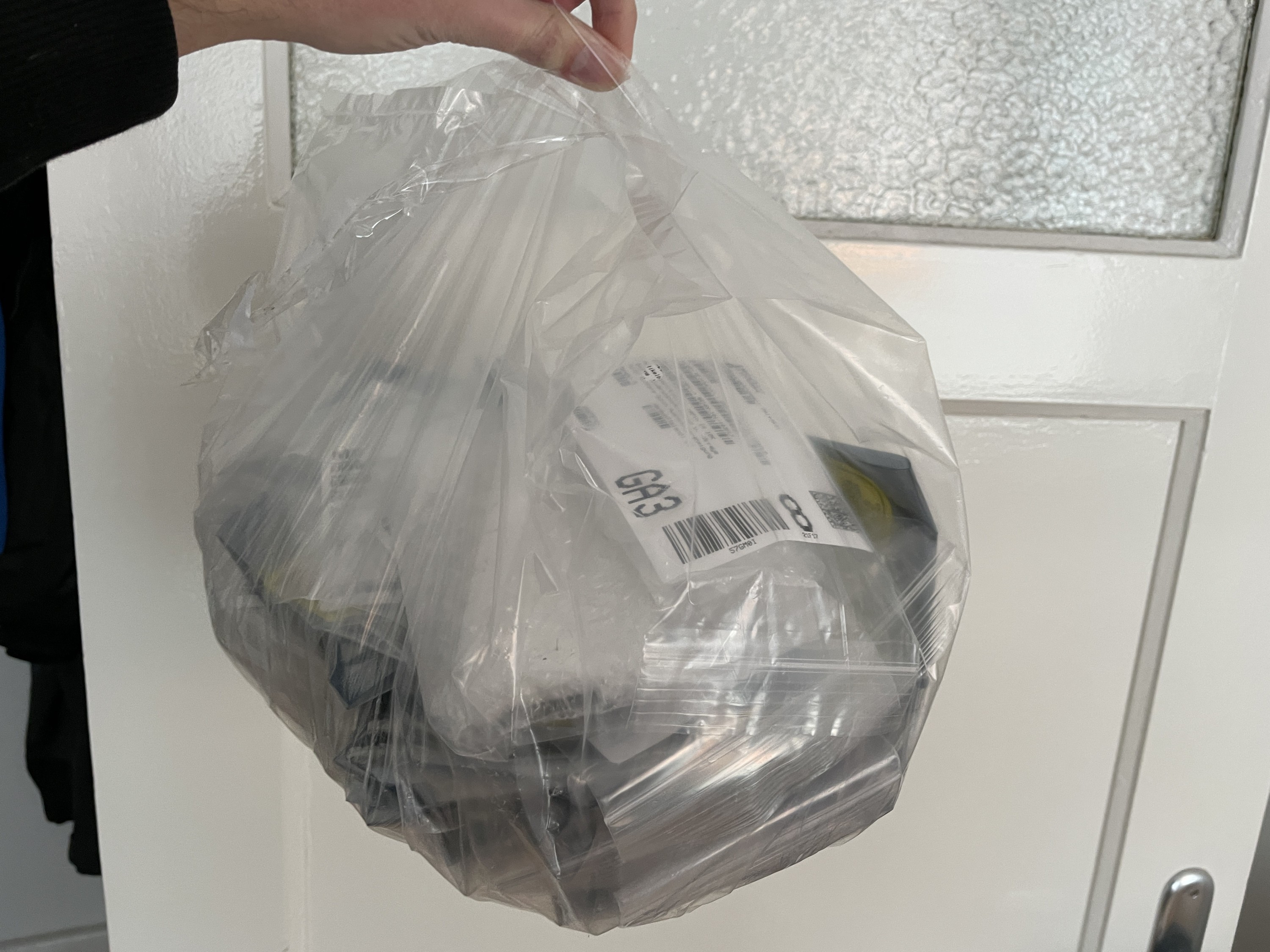
This very large bag of parts was ordered from Mouser:
First parts, resistors, IC sockets and quarz crystals were installed:

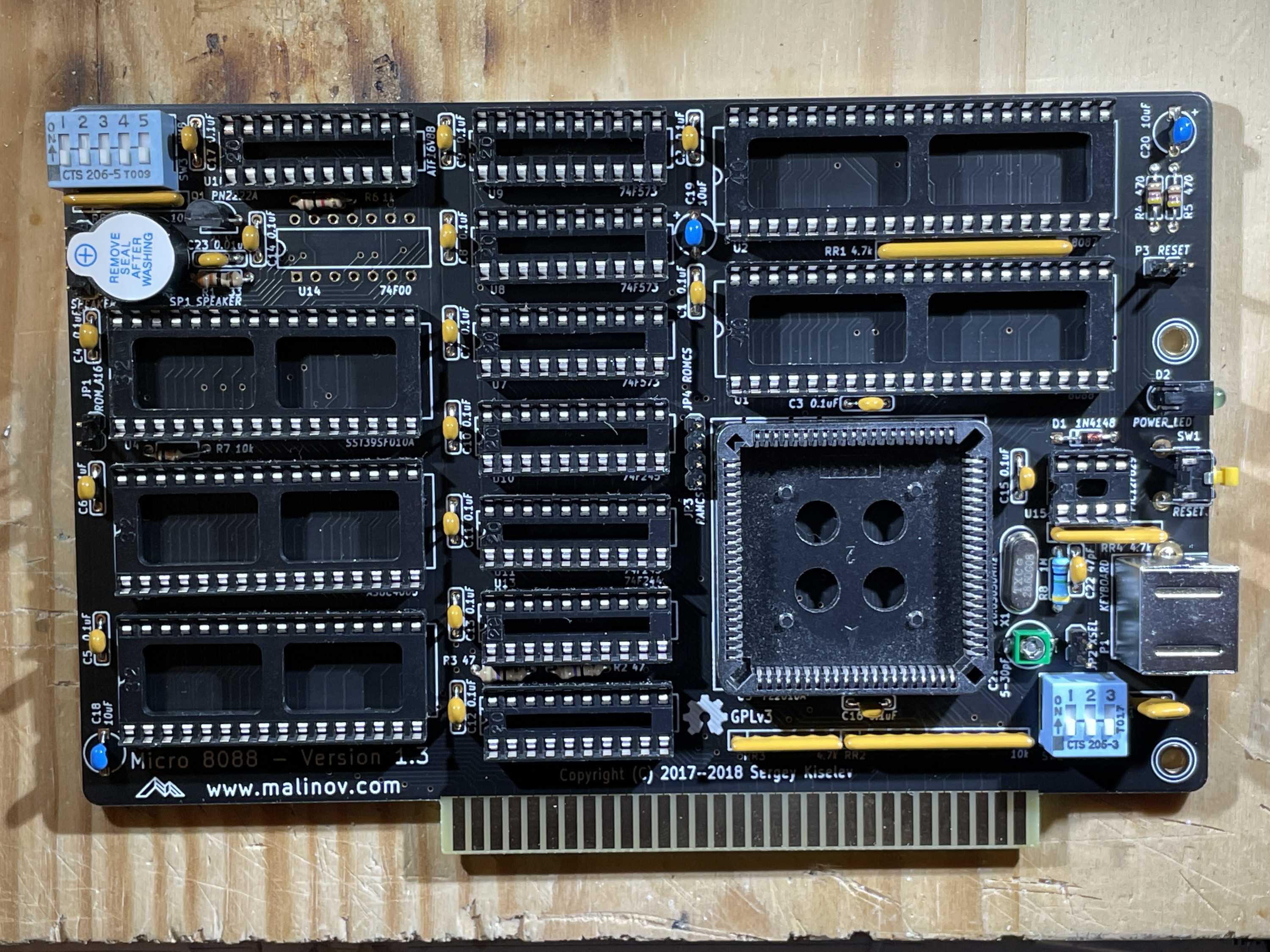
Resistor networks, PLCC sockets and decoupling capacitors:


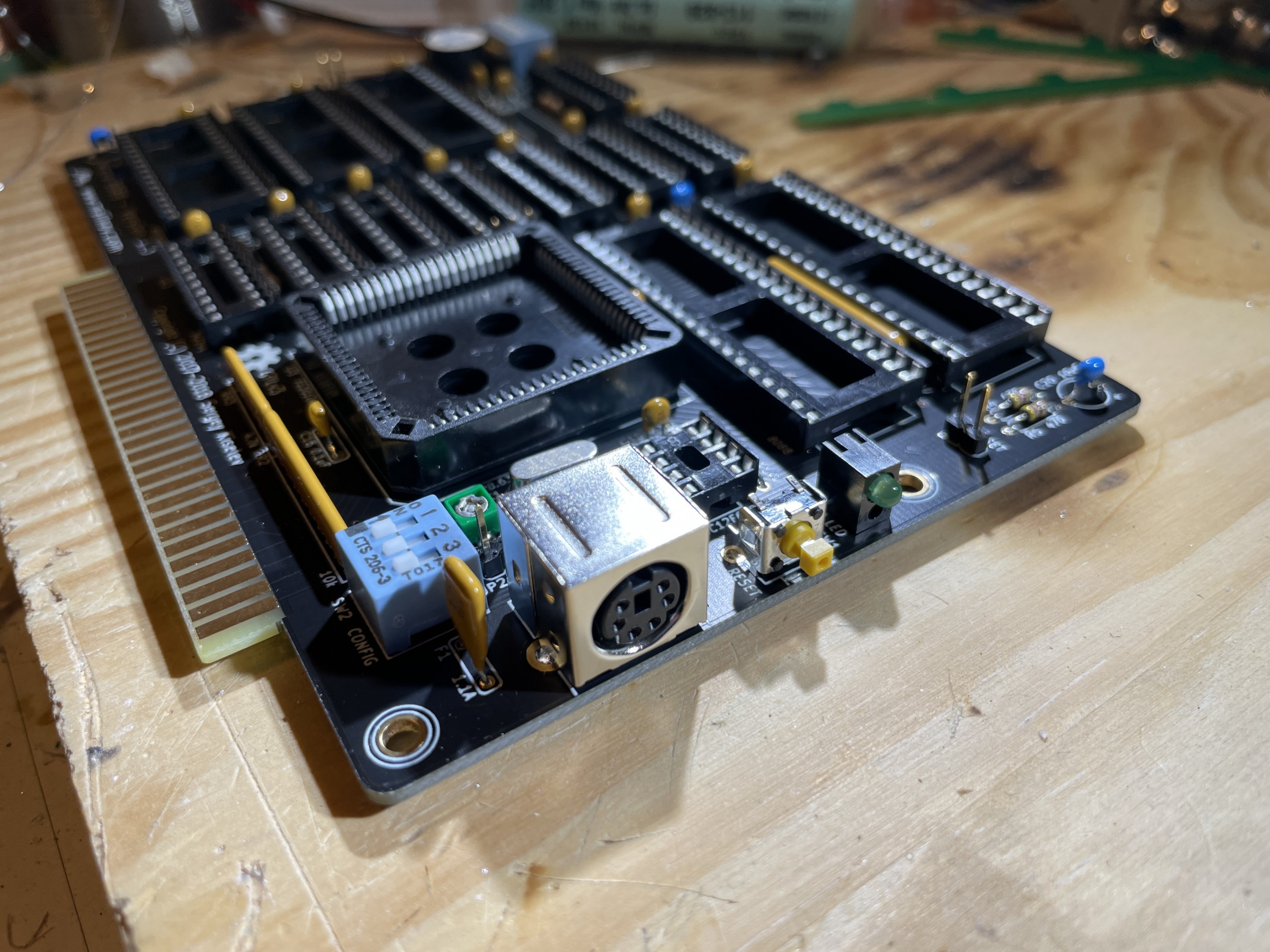
DIP switches, piezo buzzer, PS/2 jack, reset switch:
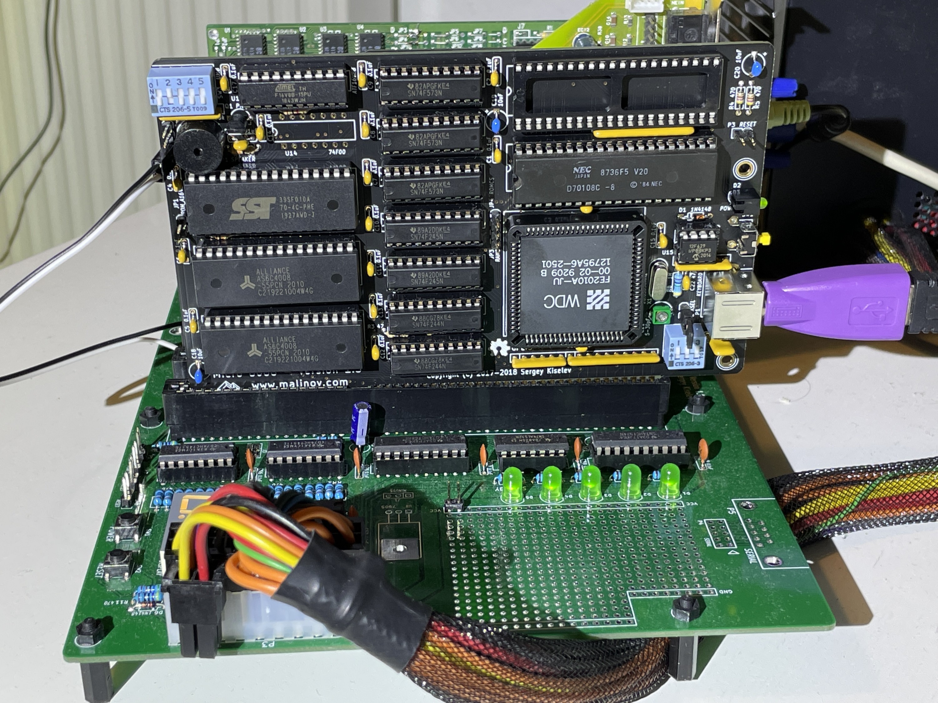
 Finished card, with chips and ROMs:
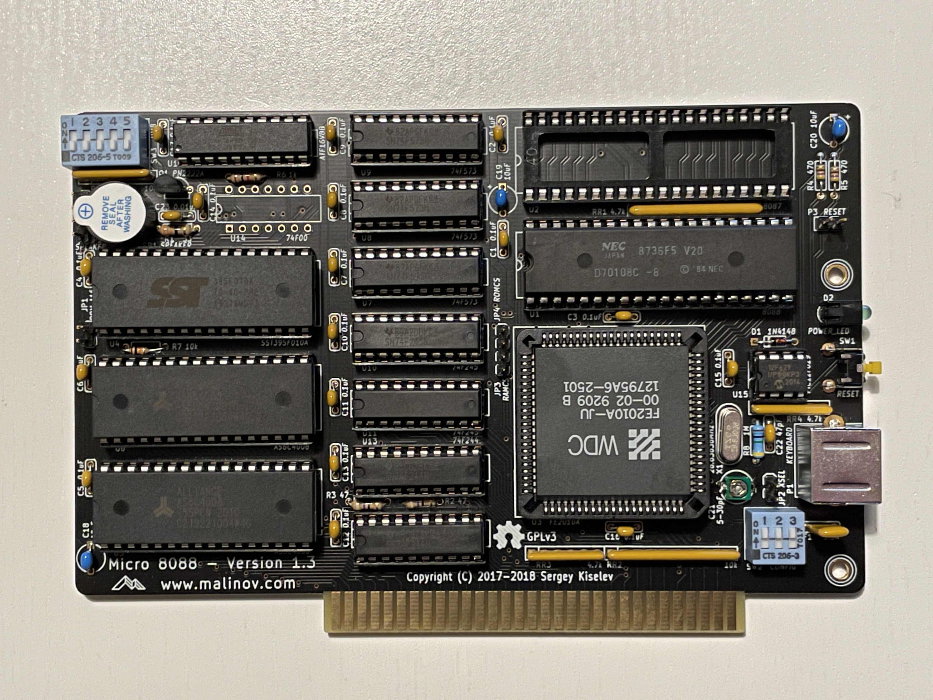
- 2x 512 KiB SRAM
- 128 KiB EEPROM (BIOS)
- >640K memory handling and PC speaker are controlled by a ATF16V8
- PIC12F629 converts PS/2 scancodes & protocol into regular PC XT scancodes
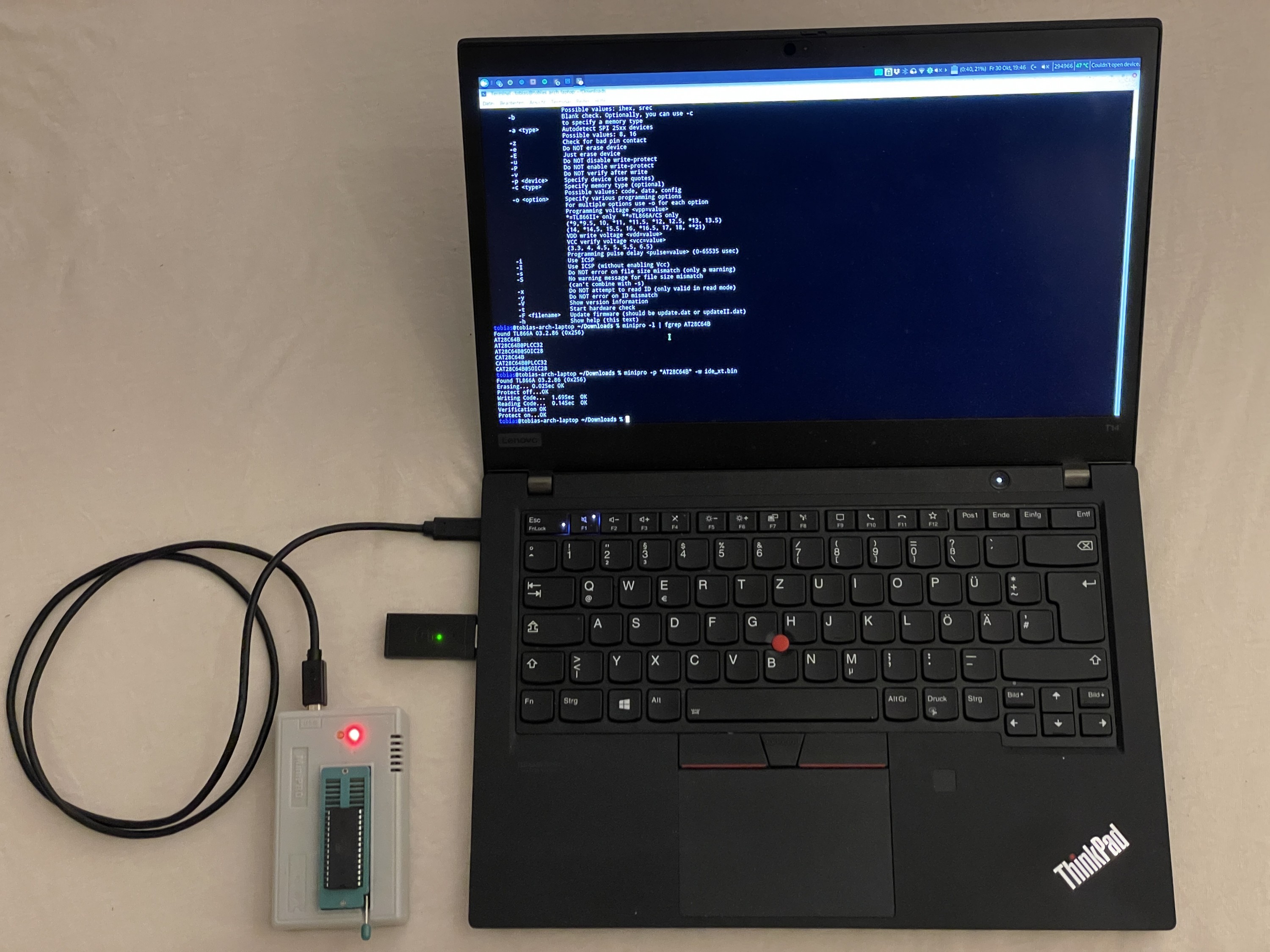
Chips were all programmed using a MiniPro TL866. All ROM files are present in the Git repo for micro8088.
Last thing to do was to set 2 jumpers, XSEL (28 MHz crystal) and one across the 4pin speaker header to enable the internal piezo buzzer.
DIP switches on SW2 were set to ON, ON, ON, to configure VGA graphics and E0 scancode passthrough.
The second DIP switch (responsible for memory mapping above 640K) was set to 0xC8000, so SW3.2 = ON.
XT-CF card (XT-IDE)
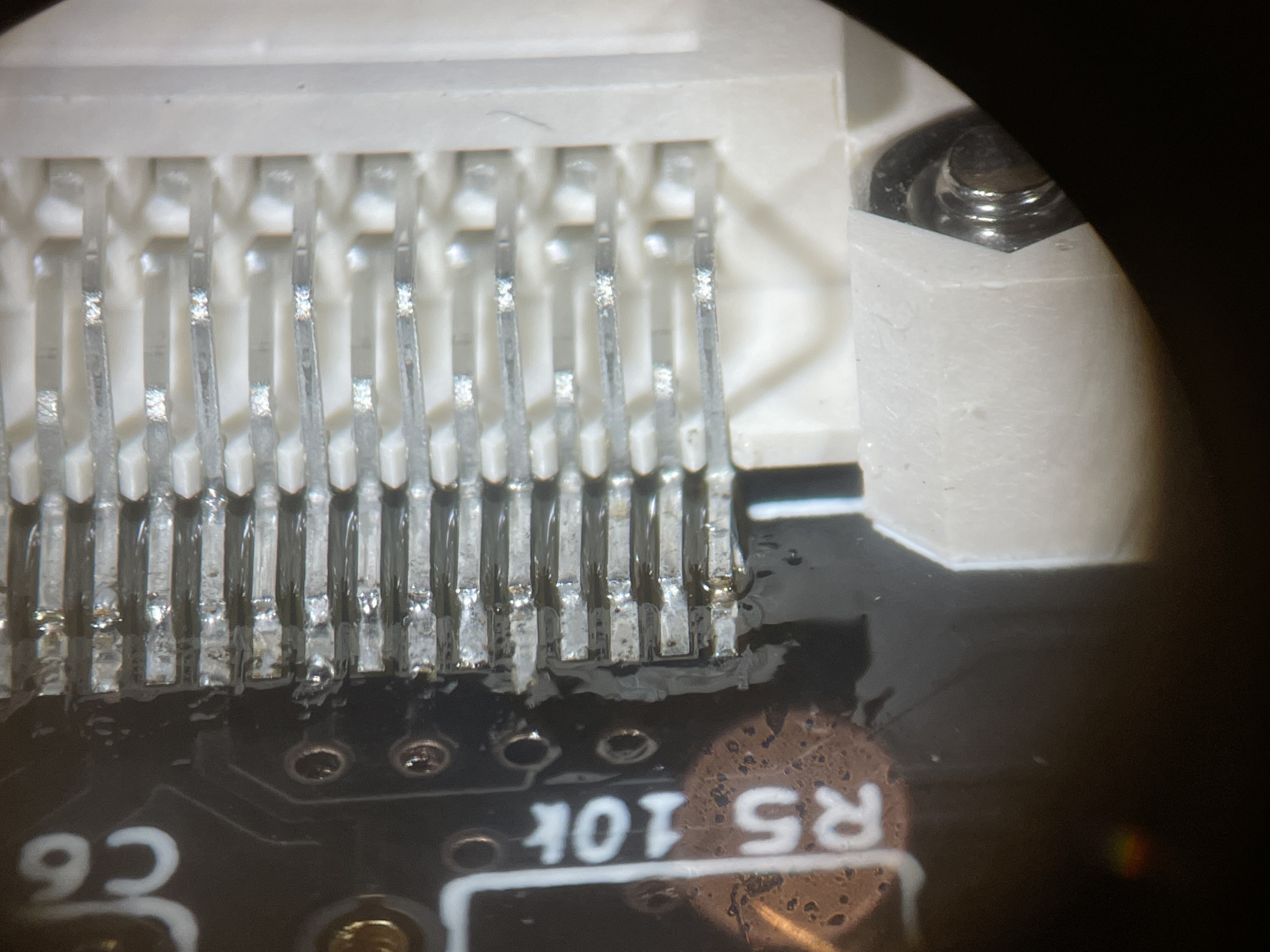
The XT-CF Lite v4 card uses a CF card socket, directly screwed to the PCB using M2 bolts and nuts. This also makes alignment of the SMD pins very easy. After that, some decoupling caps were installed.
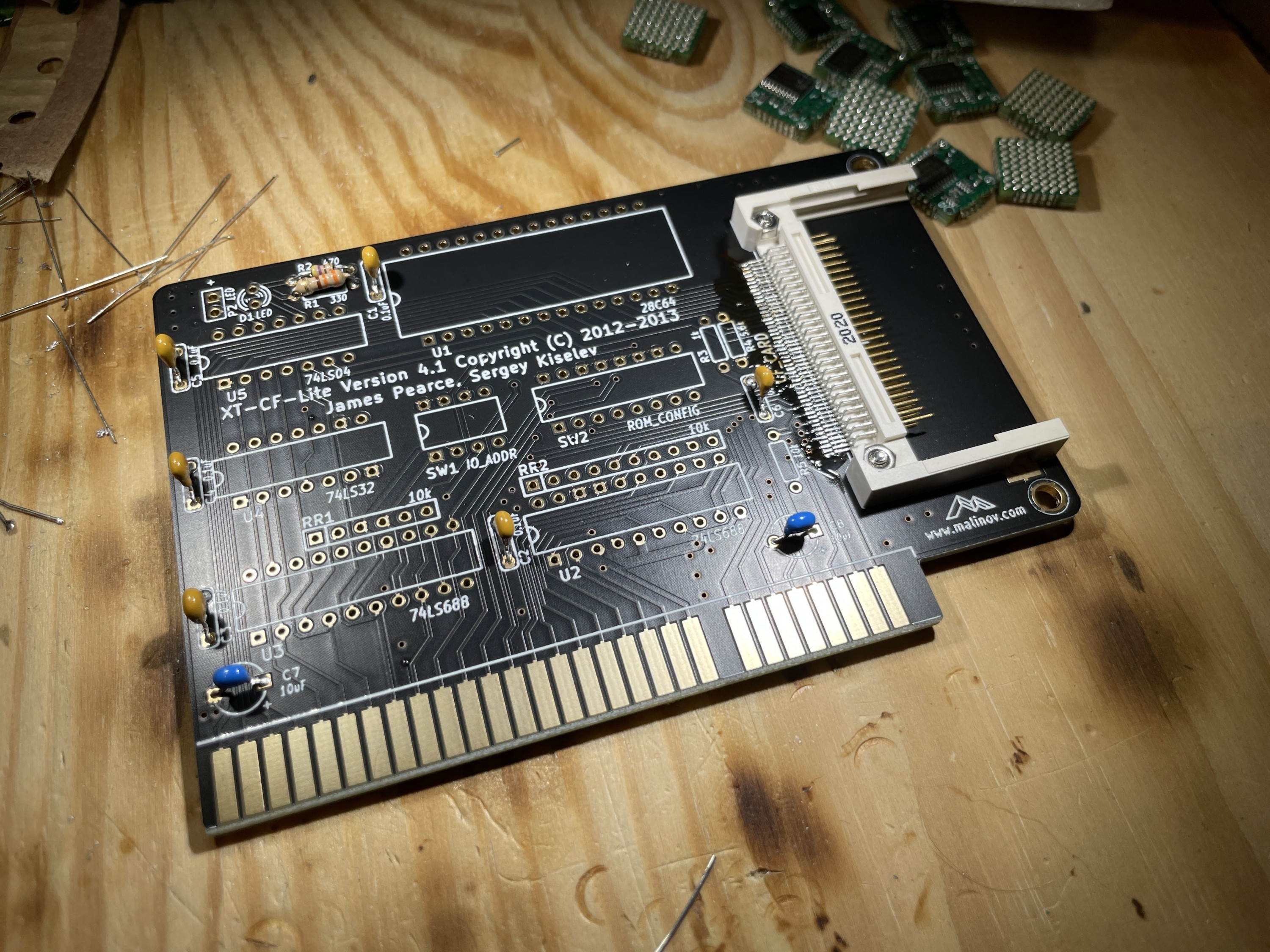
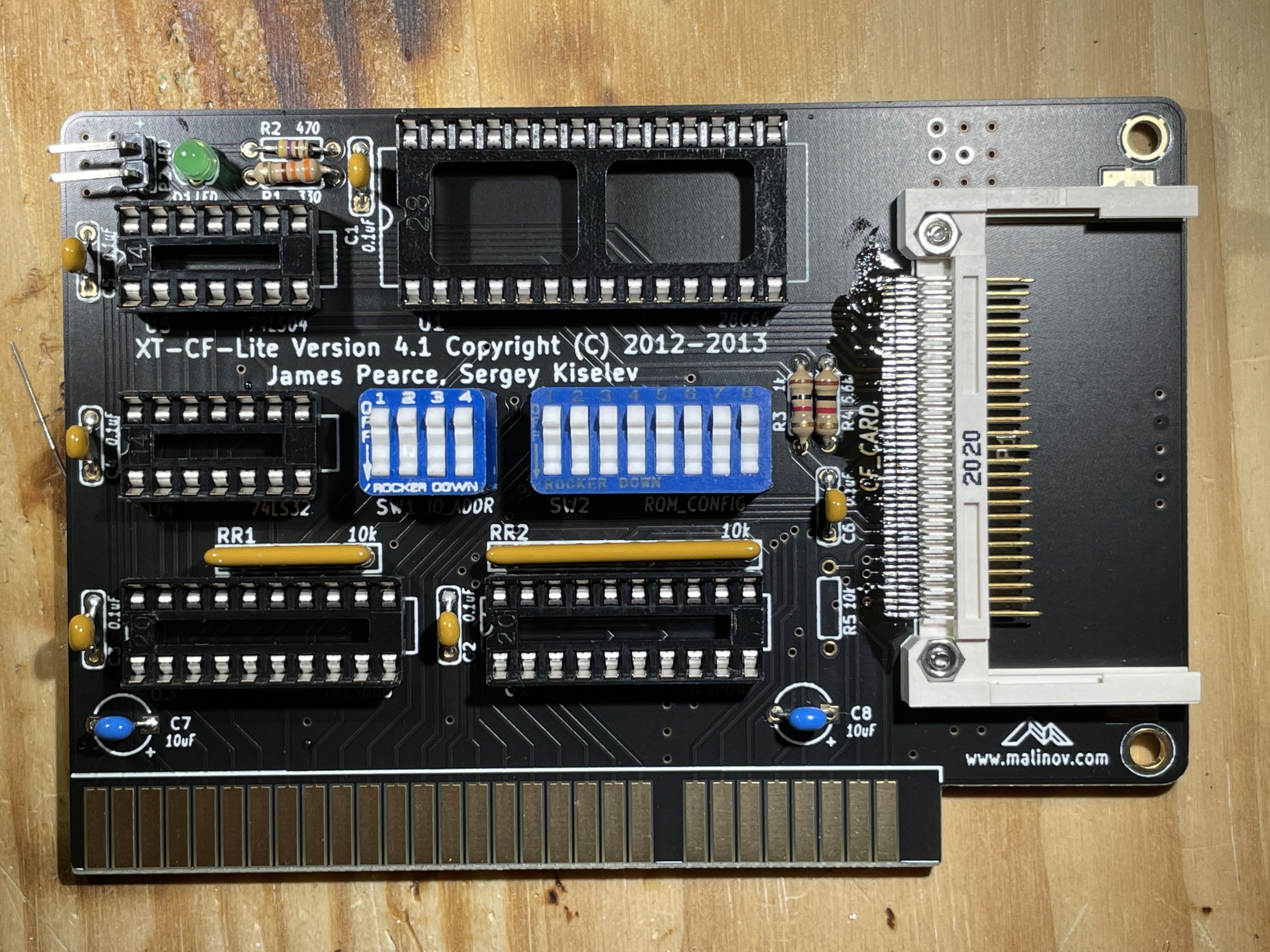
IC sockets, resistors and DIP switches followed:

The card was then ultrasonically cleaned to get rid of any flux (from the CF card socket).
The XT-IDE Option ROM was programmed onto the EEPROM using a MiniPro again.

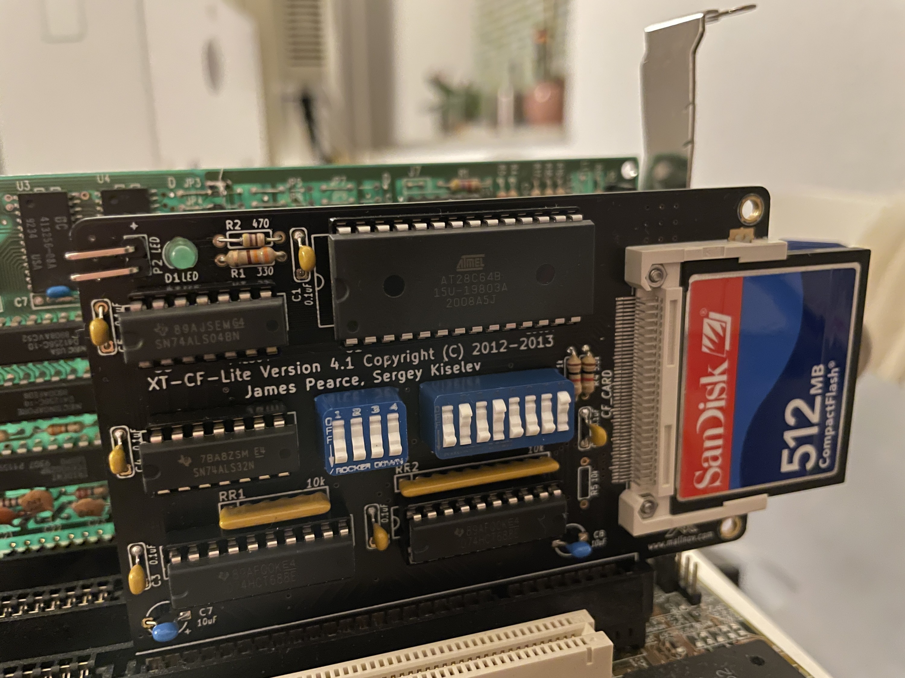
Finished card, installed into an ISA slot:
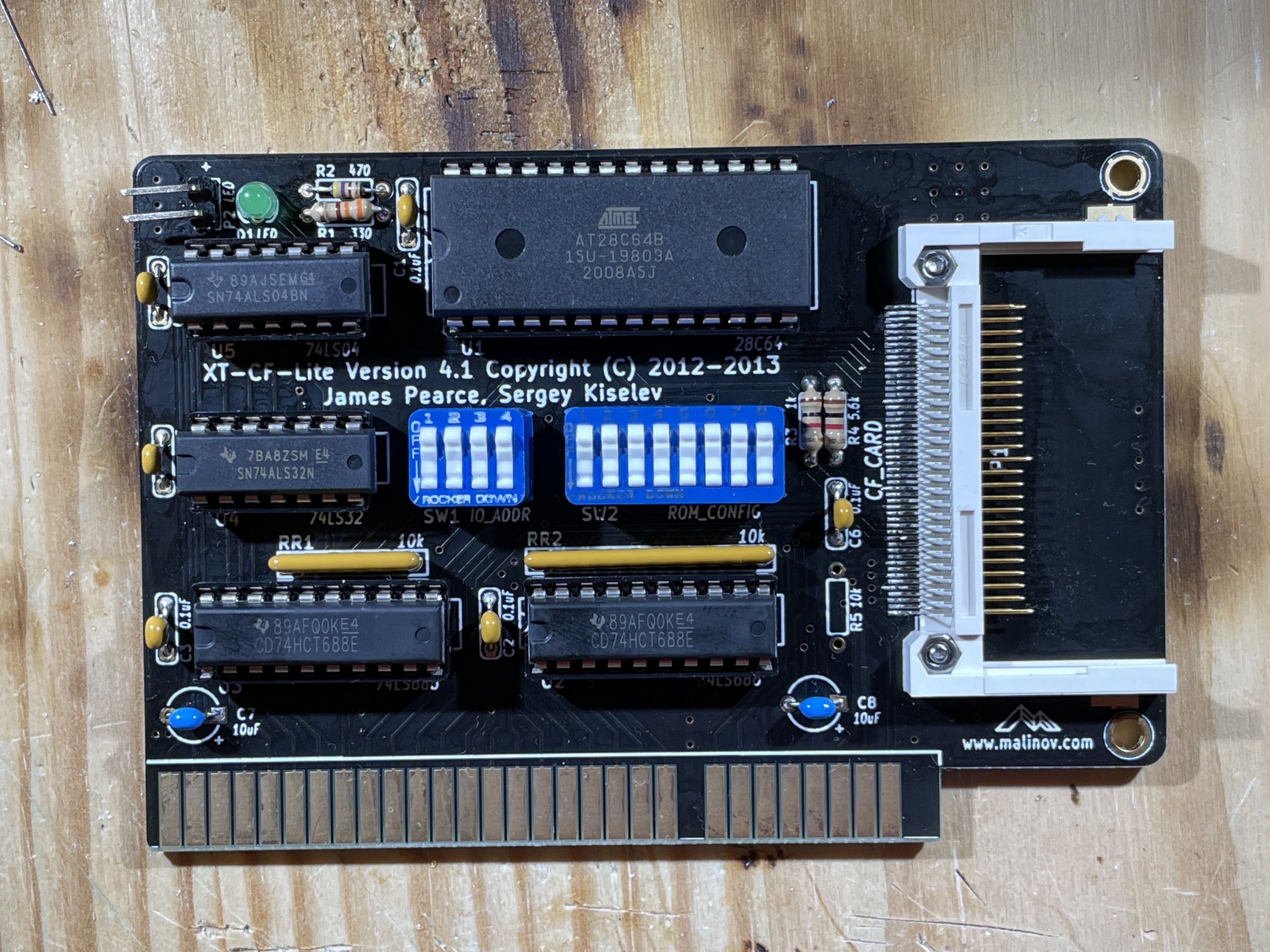
DIP switches were configured to:
- I/O address 0x300
- EEPROM active
- EEPROM write inactive
- BIOS address 0xD0000
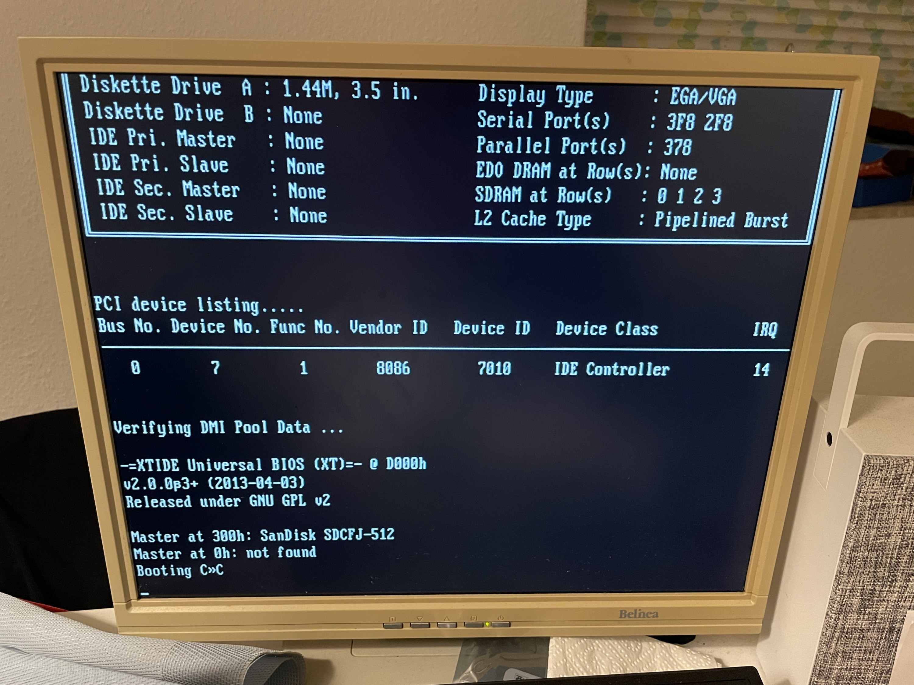
Testing the card individually (in a more modern Pentium/Socket 7 mainboard) shows that both the card itself and the XTIDE BIOS are working correctly:
Game Blaster (MUS-1099) clone sound card
After watching a YouTube video by “Necroware” about a SoundBlaster 2.0 Game Blaster retrofit, I looked for a stand-alone Game Blaster clone project.
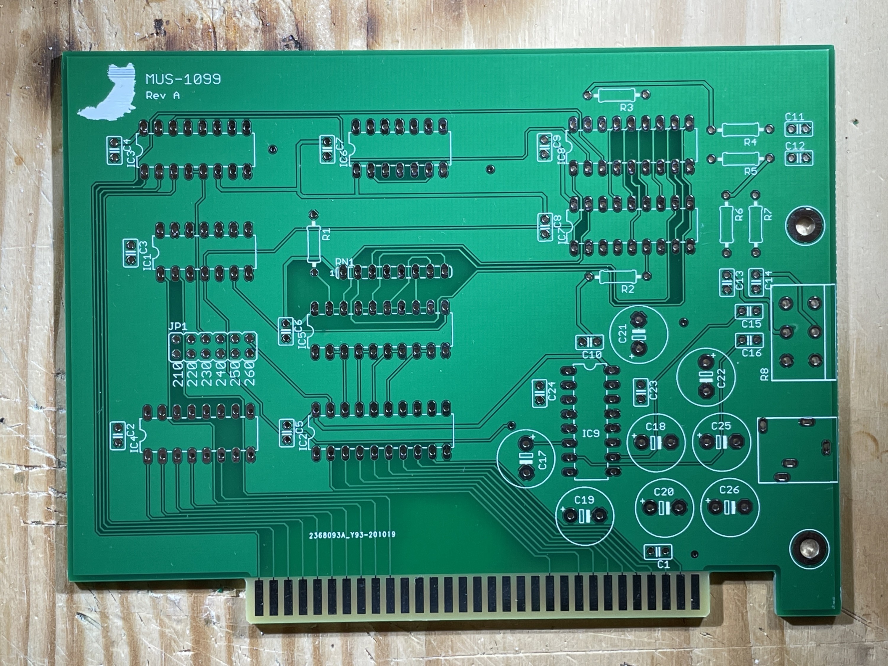
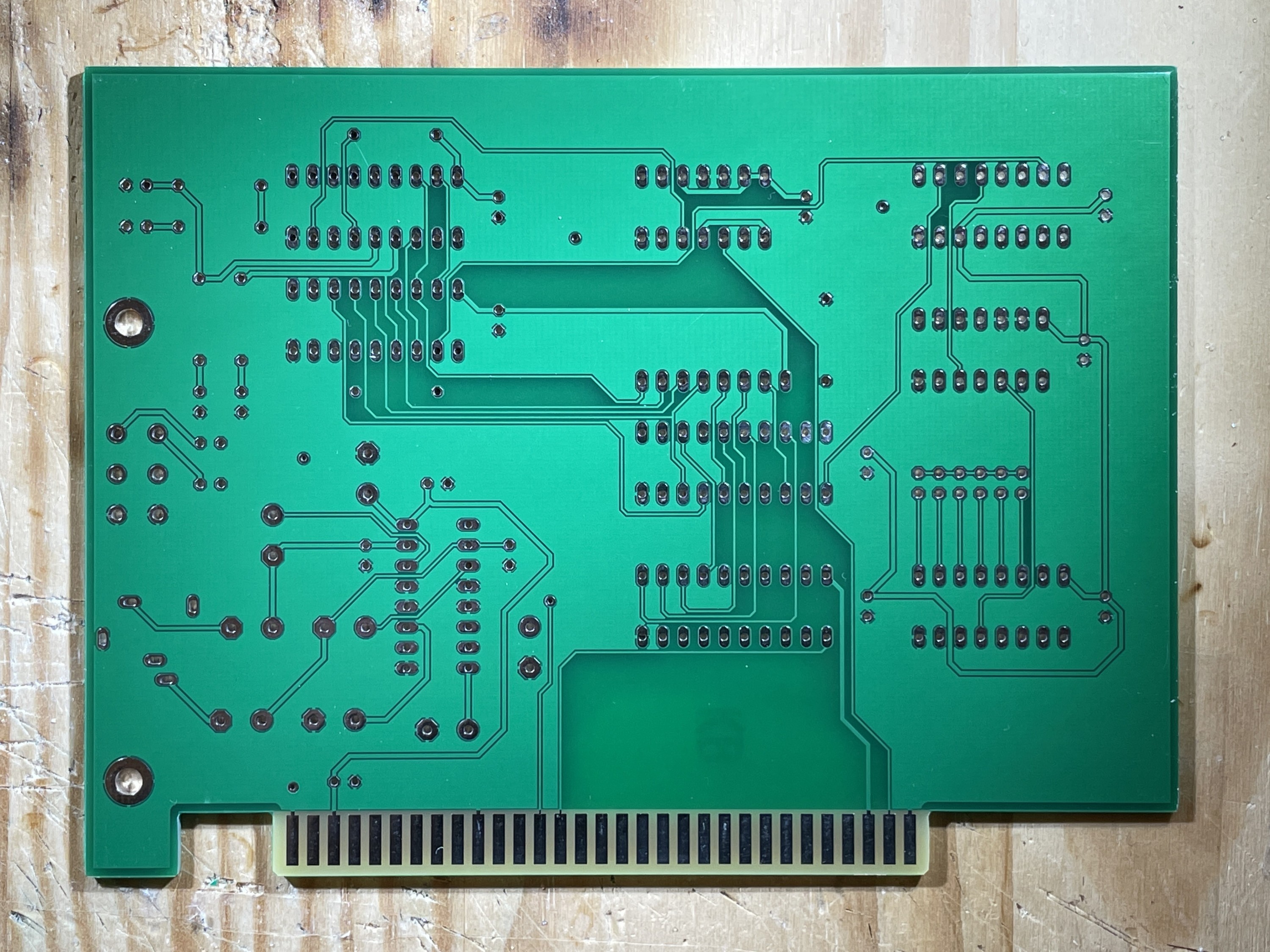
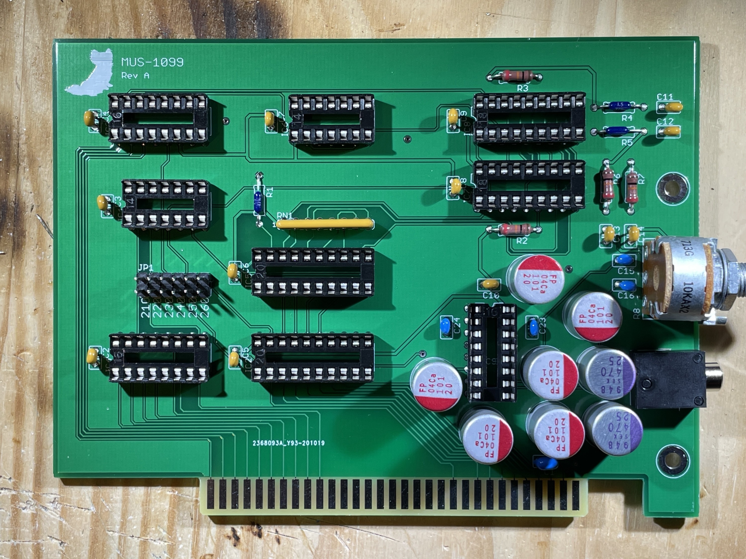
I found the MUS-1099 card on GitHub and ordered some PCBs. This was done before the Micro8088 project itself, which is why the PCB color and surface finish are different:
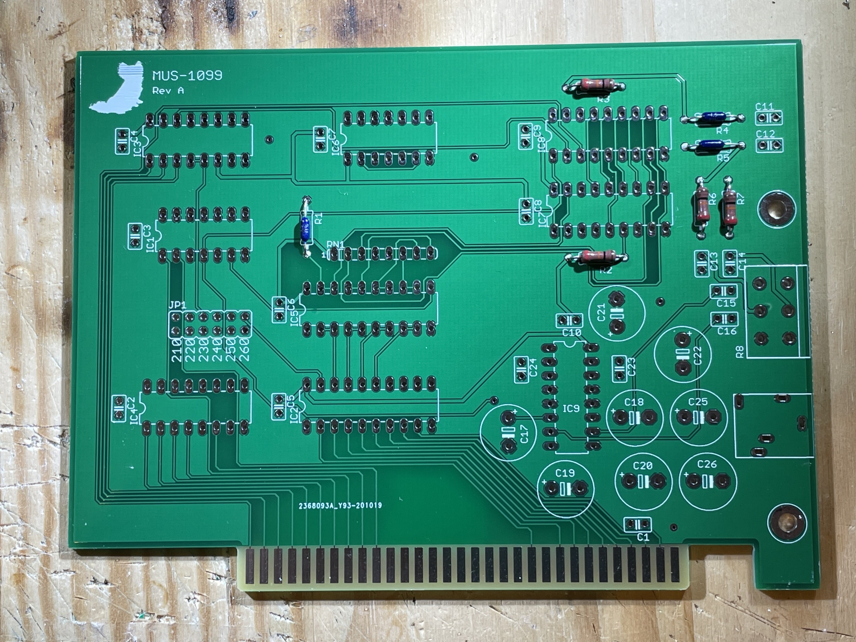
Assembly started with resistors and decoupling caps again:
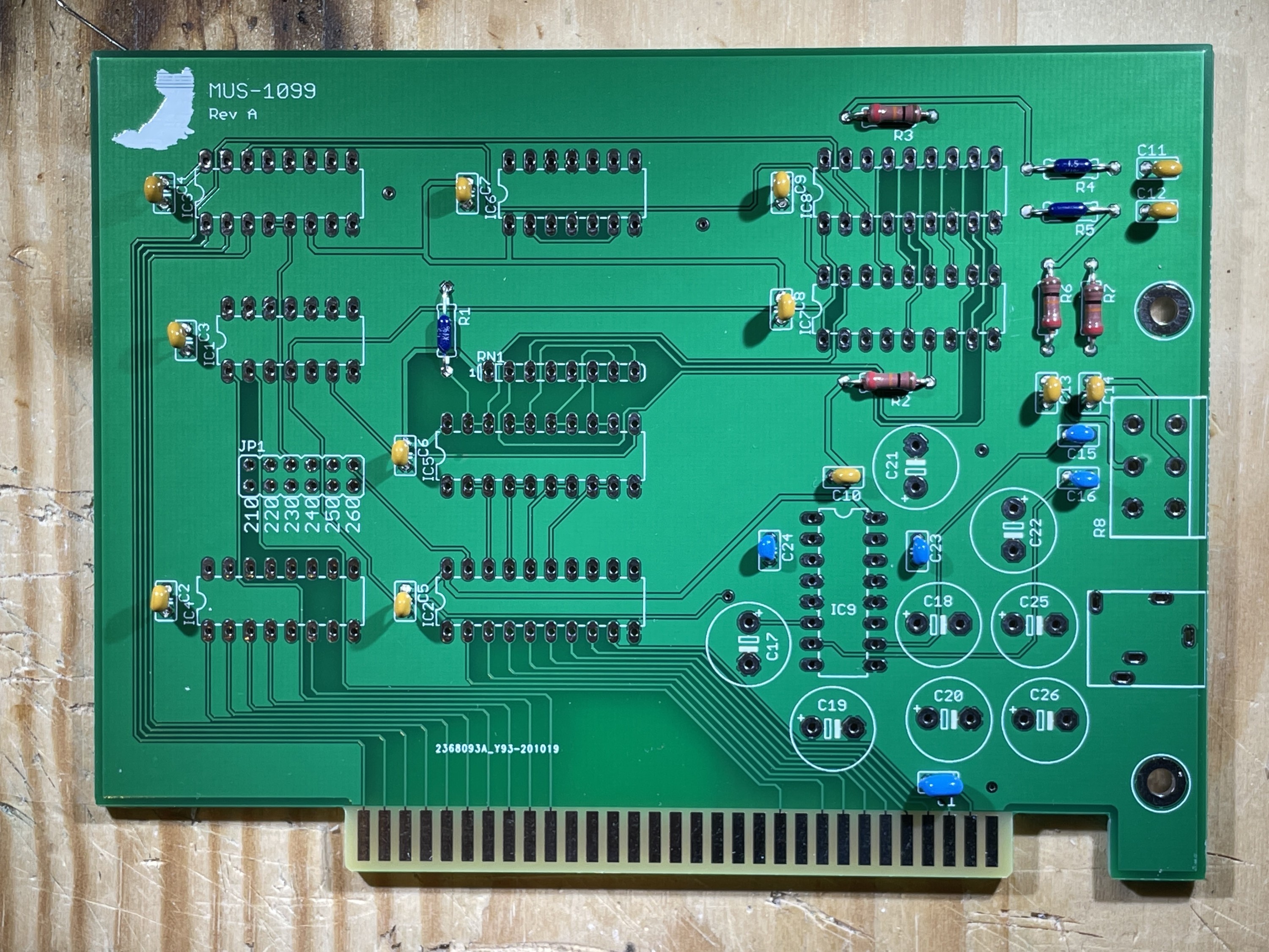
DIP IC sockets and resistor networks were installed.
I also went overboard by installing solid polymer capacitors for the audio circuitry. That isn’t required at all, significantly more expensive than electrolytic capacitors and won’t really have any benefit other than long life/stability.
Still: They look pretty and I had them at hand.


The (rather unusual) stereo potentiometer for volume control and the 3.5mm audio jack were then installed.
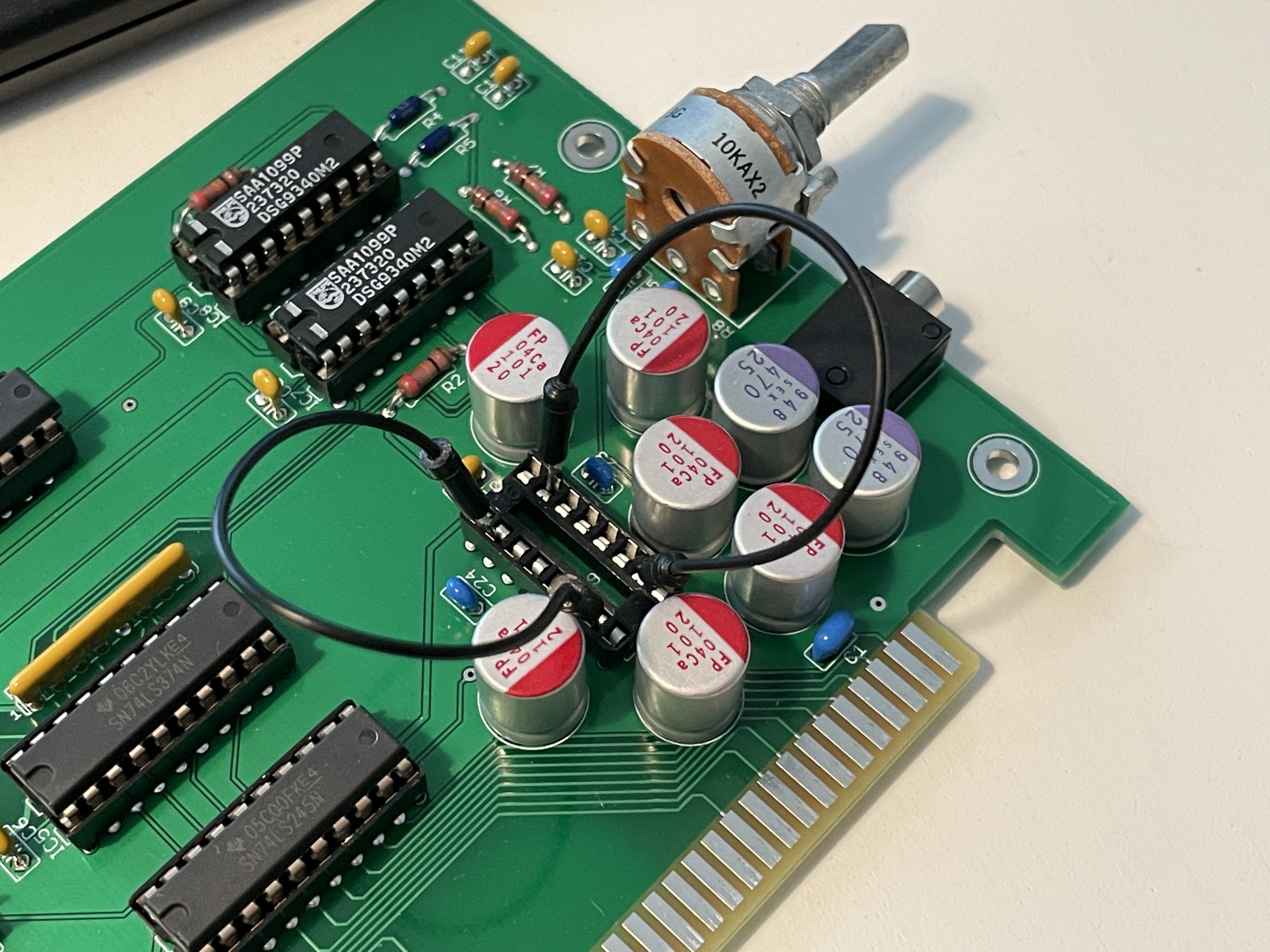
The 74-series logic ICs were also inserted into the PCB.

After installing the SAA1099 synthesizer chips and testing the card inside the Micro8088, I noticed that the audio levels were extremely high. Even with the volume potentiometer turned all the way down, I was getting a lot of hiss/noise and the audio level was way to high for my active speakers. I then removed and bridged the TEA2025 amplifier IC:

The sound card in action (playing Monkey Island 1):
I also tested Arkanoid 2 and Leasure Suit Larry 3 succesfully. Moving the CMS.DRV file from LSL3 to Space Quest 3 did not work.
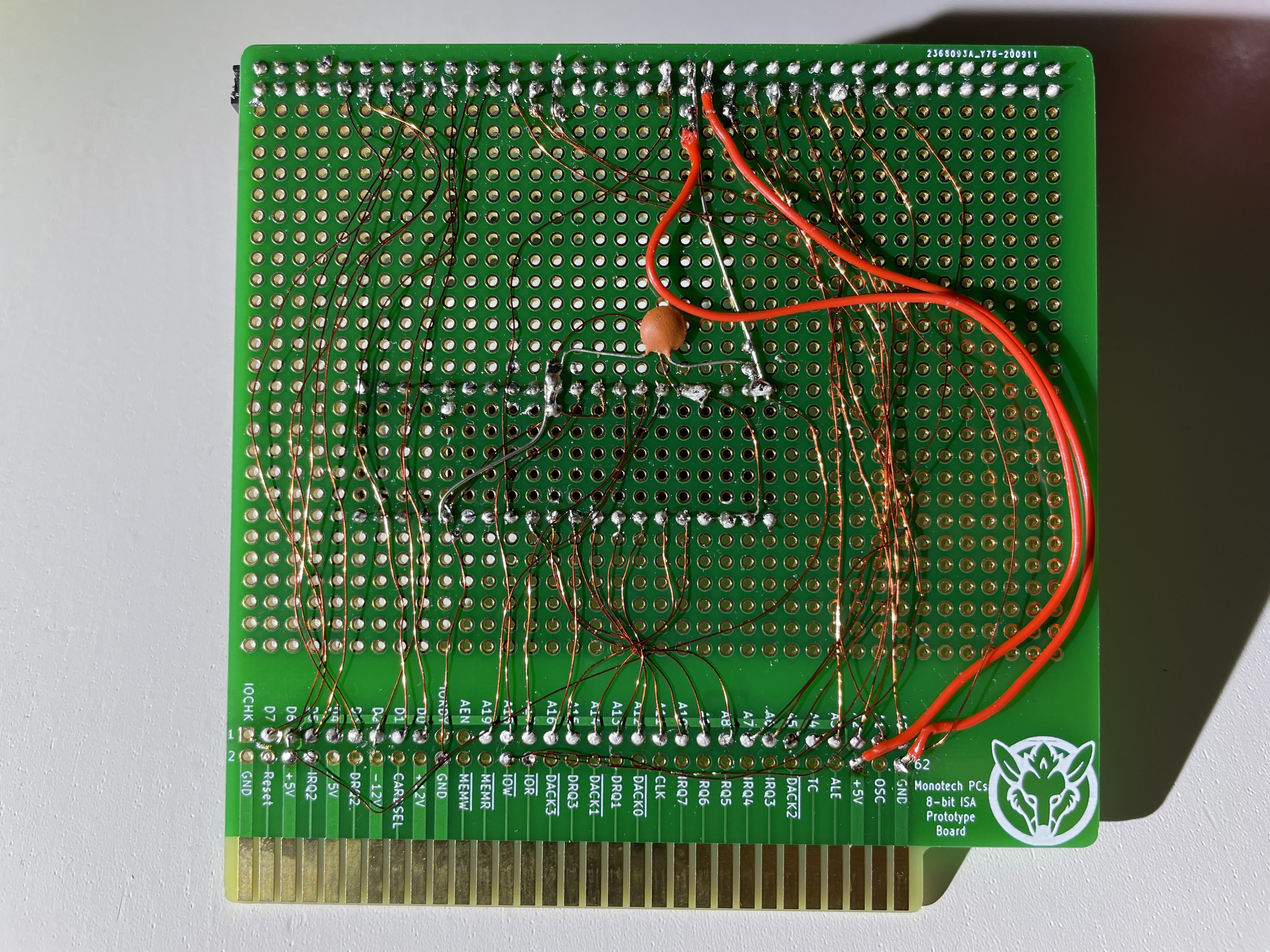
ISA8019 prototype
To get network access without having an actual ISA network card around, a prototype ISA card was wired up to a RC2014 (Z80 minicomputer) network card. PHPPLD was used to generate a bitstream of the ISA bus address decoding EEPROM/PLA.


Altough the card could be initialized and configured right away, all network packets sent were corrupted. Every odd byte in packets was 0xFF, resulting in totally broken Ethernet frames (and no connectivity, of course). After double and triple-checking the card itself, I noticed that the NE2000 packet driver by Crynwr Software was trying to do 16bit bus accesses.
After finding and installing a modified version by user profdc9, packets were sent/received properly and the card could be used.
A proper (8/16-bit capable, PXE ROM, configurable) ISA card was designed later as the ISA8019 project.
Here’s the micro8088 computer with RC2014-to-ISA NIC, going online to download a tracker module and chatting on IRC: